features

[For beginners] Self study column by TAKISAWA staff: What is lathe? -About turret-

Others

2022.10.18

#Beginner

#Human resource development

#Lathe manufacturer


In the previous column, we have covered what is “spindle.”
This time, we will explain more deeply about the turret.
Just as the previous column, the indicators will also be explained using the “TCN-2100” product catalog.


Click here to look back the previous columns.
Click here for “Overview of lathe”:
Click here for “About spindle”:


Do you remember what a turret is?
JIS (Japan Industrial Standards) defines a turret as “a base to which cutting tools are attached.”

1. Detail of the Turret

Fig. 1 Turret on lathe


Figure 1 illustrates the part inside the green frame is the turret, which we will be explaining in this article.
 
First, the keywords associated with turret.
Turret:… holds two or more tools radially and rotates to select a tool to cut with (known as indexing).
Let’s take a look at the actual photo of a turret (Figure 2).

Figure 2: Diagonal View of the Turret


The tools are radially placed on the turret, Once the turret receives command from the NC unit, it indexes to position tools to be used for cutting.
This type of turret is mainly used on current NC lathes we see today.
As described later in Figure 3 (shown below), the number of attachable tools is expressed “T8” and “T12”.

2. Explanation of each Indicator

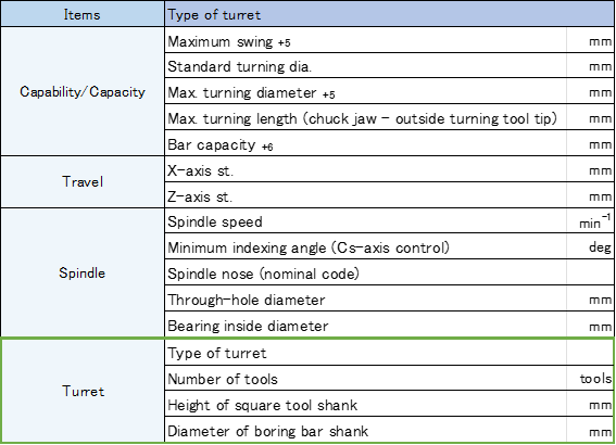
Table 1 Indicators listed in TCN-2100 catalog

Number of attachable tools
• T8 represents a turret that can hold eight (8) tools.
• T12 represents a turret that can hold twelve (12) tools.

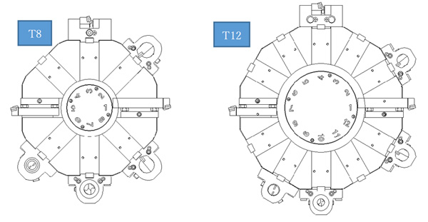
Fig. 3 Turret (T8 and T12)


Height of square tool shank: The size of the square tool that can be held.
Diameter of boring bar shank: The diameter of the boring bar that can be held.

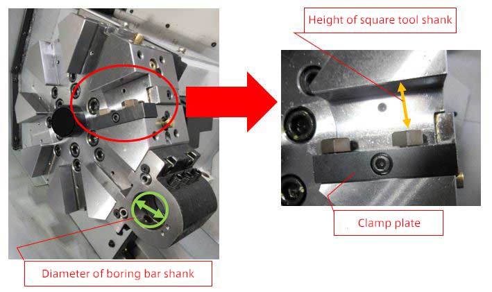
Fig. 4 Square tool shank and diameter of boring bar shank


As illustrated above in Figure 4, these two areas provide space to attach tools (square tool and boring bar).

Do you know how the tools are attached?
 
The components of each part and how they are attached are shown below.
 

[Attaching a square tool]

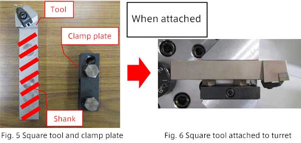
“Shank” is the part diagonally shaded in red.
“Clamp plate” is used to hold down and fix a tool.
 

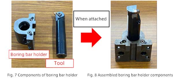
[Attaching a boring bar]

O.D./end face machining ⇒ Square tool
I.D. machining    ⇒ Boring bar             
The above tools are most commonly used.
 

Many terms have appeared also in this column!
They are explained on the page below.
Click below to learn more!

Machine Tool Terminology


Click here for TCN-2100.